
A gear is defined as “a toothed wheel that works with others to alter the relation between the speed of a driving mechanism (such as the engine of a vehicle) and the speed of the driven parts (the wheels).”
Gears are, basically, a means of transfer of motion.
TABLE OF CONTENTS
GEAR RATIO
A gear ratio is a direct measure of the ratio of the rotational speeds of two or more interlocking gears. The gearing ratio is the value at which you change your velocity and torque. Again, it has a very simple equation. The gearing ratio is just a fraction which you multiple your velocity and torque by. Suppose your gearing ratio is 3/1. This would mean you would multiply your torque by 3 and your velocity by the inverse, or 1/3.
How to calculate gear ratio- As a general rule, when dealing with two gears, if the driving gear (the one directly receiving rotational force from the engine, motor, etc.) is bigger than the driven gear, the latter will turn more quickly, and vice versa. We can express this basic concept with the formula Gear ratio = T2/T1, where T1 is the number of teeth on the first gear and T2 is the number of teeth on the second.
For more details, refer here
Achieving a particular ratio- If you wanted a simple gearing ratio of say 2 to 1, you would use two gears, one being twice as big as the other. It isn’t really the size as much as the diameter ratio of the two gears. If the diameter of one gear is 3 times bigger than the other gear, you would get a 3/1 (or 1/3) gearing ratio. You can easily figure out the ratio by hand measuring the diameter of the gears you are using.
For a much more accurate way to calculate the gearing ratio, calculate the ratio of teeth on the gears. If one gear has 28 teeth and the other has 13, you would have a (28/13=2.15 or 13/28=.46) 2.15 or .46 gearing ratio. We’ll go into this later, but this is why worm gears have such high gearing ratios. In a worm gear setup, one gear always has a single tooth, while the other has many - a guaranteed huge ratio. Counting teeth will always give you the most exact ratio.
GEAR EFFICIENCY
Adding gears to the system leads to loss in power, due to friction, misalignment of pressure angles, gear backlash, etc. Different gears have different efficiencies, obviously. We’ll look at the efficiencies of various kinds of gears as we move ahead.
DIRECTION OF GEAR ROTATION
When there are an even number of gears, the direction of rotation of the last gear is opposite to that of the first. We can see this from the tangential velocities at the point of contact. Similarly, in case of odd number of gears, the direction of rotation of the last gear is same as that of the first.
Gear Chains- Suppose you have 30 gears (holy squirrels!), all in order. How in the monkies do you calculate the gearing ratio of that behemoth? Easy. Ignore all the gears in between the very first and very last gear. If the diameter of the first gear is 2 inches, and the diameter of the last is 1 inch, you have a 2:1 ratio. The gears in between do not matter. Now what direction does the last gear rotate? Easy, you have an even number of gears, so it is counter-rotational of the first gear. What efficiency do you have? Well that’s: Total efficiency = gear_type_efficiency ^ (# of gears - 1) = 0.9 ^ (29) = 4.7 % If instead you used 5 gears, you would have: Total efficiency = 0.9 ^ (4) = 65.6 %
COMPOUND GEARS
When we have two gears on the same shaft, it’s a compound gear. The speed of rotation will be the same, as they are on the same shaft.
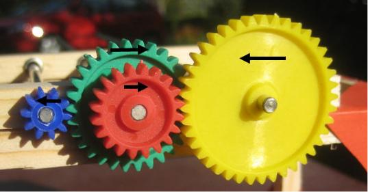 The center one is a compound gear.
GEAR PITCH
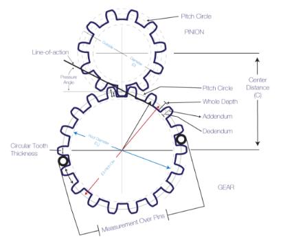
Circular Pitch- the distance between corresponding points of consecutive gear teeth measured along the pitch circle.
Diametral Pitch – the quantity of teeth per inch of the diameter.
TYPES OF GEARS
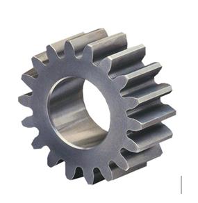
Spur Gear
Spur Gears are the most common type of gears. The design is simple, hence they are easy to manufacture. Manufacture and maintenance are economical. They impose only radial thrust on the bearings. Disadvantage is that they produce a lot of noise, and the noise can become really intolerable at high speeds. Efficiency is approximately 90%.
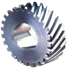
Helical Gears
Gears having teeth inclined at some angle to the shaft. The teeth look like they’re forming a helix, hence the name. The angle of inclination, however, shouldn’t be too large, as it affects the power transmission, and also reduces the lifetime of the gear. These gears can take higher loads than spur gears. The motion of helical gears is smoother and quieter than spur gears, hence these can be used at high speeds. These impart both radial loads and thrust loads on their bearings. Efficiency of helical gears is approximately 80%.
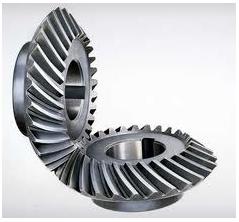
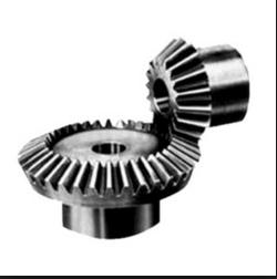
Bevel Gear
Bevel Gears are used when the direction of a shaft’s rotation needs to be changed. They can be inclined at any angle, but the most common ones are inclined at 90 degrees. Efficiency is approximately 70%.
Spiral Bevel Gears-
Zero Bevel Gears -
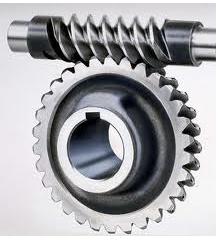
Worm Gear
Worm Gears are used when large power reductions are needed. The worm resembles a screw, and the gear which is in contact resembles a spur gear. The worm gear is not back-drivable, which means only the motor can drive it, and it won’t be affected by gravity and other counter-forces. Efficiency is approximately 70%.
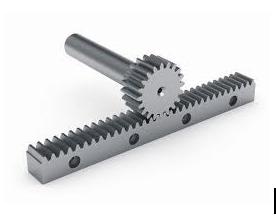
Rack and Pinion
Ever wondered what converts the rotation of the steering wheel to the left-right movements of the tie rods in automobiles? The rack and pinion gears do it for you! They convert rotational motion to linear motion, with an amazing efficiency. Efficiency is almost 90%. The straight one is known as ‘rack’ and the circular one is known as ‘pinion’.
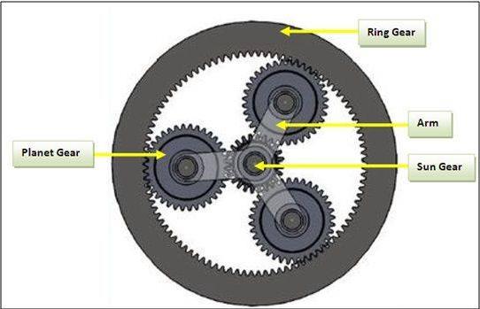
Sun and Planet Gears
If you need a really really high gearing ratio for your robot, planetary gears are the way to go! This can be used to convert reciprocating motion into rotary motion. Fun fact- James Watt used it in his early steam engines!
Here is a wonderful video explaining this gear system.