
A chassis is the physical frame or structure of an automobile, an airplane, a desktop computer, or other multi-component device. An example of a chassis is the underpart of a motor vehicle, consisting of the frame (on which the body is mounted). If the running gear such as wheels and transmission, and sometimes even the driver’s seat, are included, then the assembly is described as a rolling chassis.
The Chassis provides a rigid, safe and sufficiently strong support and protection to the driver, engine and all components of the car. It can also be described as a means of linking together appropriately all the mounting points of the car.

TABLE OF CONTENTS
- FRAME
- MOTOR MOUNTING
- SERVO MOUNTING
- MOUNTING ROBOT BATTERIES
- MOUNTING SENSORS
- WHEELS
- MOUNTING YOUR ROBOT WHEEL TECHNIQUES
FRAME
The material that can be used for the chassis is
- Acrylic
- Aluminium
- Wood
Acrylic
Advantages:
- Light Weight
- Easy to work with (cut and drill)
- Transparent sheets availablewhich can be used in robots where internal mechanism is to be displayed
Disadvantages:
- On application of load it bends
- Brittle and fragile
- Unable to sustain shocks and powerful jerks during impacts or jumps
- Not reliable for long term usage of machine
Aluminium
Advantages:
- Lightweight
- Easy milling (compared to other metals)
- Readymade sections, bars, boxes, etc. are easily available in the market which can be directly used
- Higher strength to weight ratio.
Disadvantages:
- Sheet of same dimension is very heavy as compared to other two materials
Wood
Advantages:
- Lightest among the three
- Relatively cheaper than acrylic.
- Easy to work with.
Disadvantages:
- Weaker than aluminum.
- Not Waterproof.
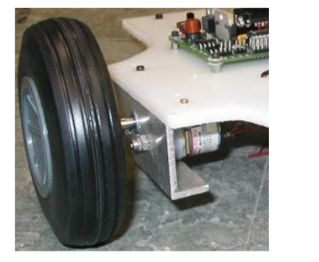
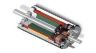
MOTOR MOUNTING
To mount any type of motor to your chassis you will need to use an L shaped bracket. For a DC motor, all you need to do is take a sheet of aluminum, drill two holes in two of the corners, drill two more holes on the other half to match the motor screw holes, then bend the entire piece in a 90 degree angle.
SERVO MOUNTING
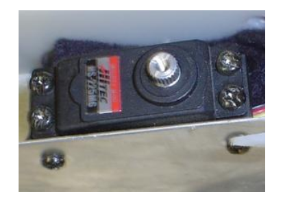
To mount your servo to your chassis, once again you will use the little baggie of goodies that came with the servo. You should have two black cube looking things with holes in it. There will be three holes in front and a single hole on the bottom. Your servo should also have four mounting holes, two on each side. Using screws, attach the front of the black things to each side of the servo. As shown in the image below, then attach your robot base with two more screws to the bottom hole of the black thingies. This particular robot used a thin reinforced sheet of aluminum as the base with two drilled holes for the mounting screws. and the completed mounted servo and wheel configuration . . .
MOUNTING ROBOT BATTERIES
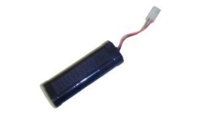
Mounting your batteries is very simple. As long as you are using an RC battery pack (such as NiCad or NiMH, you can simply mount your batteries to your robot using strips of velcro. This is the velcro that has a sticky tape side and a velcro side. The advantage to this mounting method is that you can easily swap out your batteries for freshly charged ones - great if you are in a robot competition. You can also group multiple batteries together using zip ties.
MOUNTING SENSORS
Mounting sensors is very much a case-by-case basis. What makes mounting sensors difficult is that you are very limited on where you can place them onto your robot. They must be away from noisy motors, and probably at the front/sides of your robot. You must also keep them protected so that collisions and dirt wont damage your sensors too. If your robot is a line follower, you have to keep your sensors at an exact distance from the ground or risk bad data - even when the ground is uneven! If you are lucky, your sensor has screw holes in just the right place at just the right angle. But in my experience this is very unlikely. So you must get creative, build a mount, use a little glue . . . you get the picture.
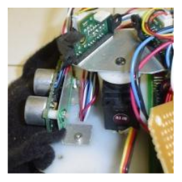
Here you see a homemade aluminum mount for a sonar transducer and another mount on a servo for two Sharp IR Rangefinders. The sonar mount is aluminum bent at 90 degrees with a few screw holes drilled into it, and plastic spacers to prevent any shorting of the circuit board with the aluminum. The IR Rangefinder mount is aluminum with double sided sticky tape holding the sensors onto the aluminum plate.
WHEELS
Wheel Diameter
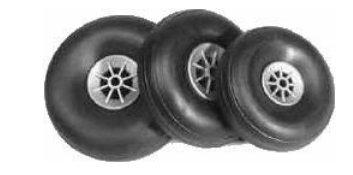
When buying (or making) your wheels you want to put your motor into consideration. For a start, there is torque and velocity. Large diameter wheels give your robot low torque but high velocity. So if you already have a very strong motor, then you can use wheels with larger diameters. Servo’s already have good torque, so you should use larger diameter wheels. But if your motor is weak (such as if it does not have any gearing), you want to use a much smaller diameter wheel. This will make your robot slower, but at least it has enough torque to go up a hill! Another dumb mistake someone can make is buying a wheel that has a diameter close to or less than the motor diameter. For example, if you have a 1” diameter motor, and a 1.5” diameter wheel, you have a .25” ground clearance ( (1.5”-1”)/2=.25” ). How high is the tallest object you want to go over?
Wheel Texture
The texture of your wheel is very terrain dependent. A common mistake for beginners is to ignore the texture of the wheel. If your wheel is too smooth then it will not have much friction. This is a serious issue with omni-wheels. An all plastic omni-wheel works poorly compared to an omni-wheel that uses rubber for the side wheels. Overly smooth robot wheels would likely skid while accelerating and braking. However a wheel that is really rough, such as a foam wheel, has higher friction with the ground leading to innefficiency. You also need to consider wear and tear on the wheel.
Wheel Width
You do not want it too wide as it causes increased resistance to rotating the wheel on a surface.
Wheel hole centre diameter
This is where you would actually mount the output motor shaft to your motor. So you must know the length and diameter of your motor output shaft so that you may put this shaft into the hole of your motor.
MOUNTING YOUR ROBOT WHEEL TECHNIQUES
Jamming
Lets start with a basic wheel attached to a basic motor. If the wheel does not have a center hole, just drill one out slightly smaller than the diameter of the shaft of your motor. Make sure the hole is perfectly centered!!!! Press fit (jam, if you will) the motor shaft into the wheel.
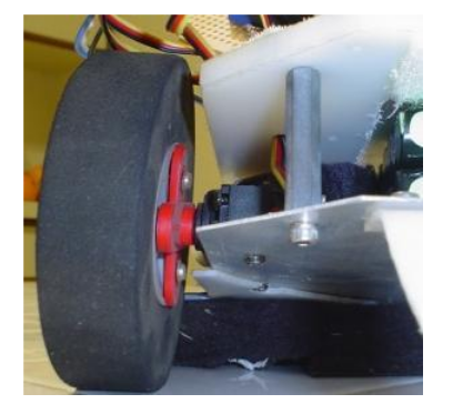
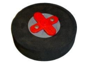
Servo Wheel Mounting
Mounting a wheel onto a servo is fairly easy, and only requires a little drilling. When you purchase a servo, you also get a bunch of other little goodies with it. One of the items is called a servo horn. This is usually a black/red circular, X shaped, or I shaped plastic piece that attaches to the output shaft of the servo. So what you do is attach the wheel to this servo horn, then just screw the servo horn as designed into the servo. In the images below, I drilled two holes into my wheel, 2 holes into the servo horn (the red X thing), and screwed 2 screws into it to hold them together. Then I just attached the servo horn to my servo output shaft with a 3rd screw.
This servo wheel mounting method, with slight modification, can work for other motors too. Just make your own custom ‘servo horn’ with a custom hole designed to fit your motor output shaft.