

Okay, so my roomie cum best friend Mohit Kherwa wanted to build a bot which would crash land into some unknown location on Mars but still find its way to the human base station. Since we were not getting a bot to Mars anytime soon, I suggested we build one that finds its way from our room to the next. And so we did. With help from wingies Shikhar Kothari and Harsh Meena.
What went inside
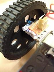
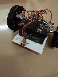
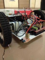
We fixed IR sensors on the front and to the left. To measure the speed or the distance covered, we made white patches on the inside surface of the black wheel. Around 10 of them. There was an IR sensor pointed at the wheel. Essentially, we were receiving a square wave as input from the sensor. Measure the frequency, and voila, you have the bot’s speed! (We learnt later that this is the principle behind a tachometer.) The bot had three wheels, one freely rotating in the front(castor wheel), and two motors (standard 2W) with the rear two, for differential mechanism. And an Arduino, motor driver shield and a 12V battery. Well, so much for the hardware.
The Algorithm
The bot’s initial position was set to origin and thus it marked the coordinate system. Y axis was in the forward direction, and x to the right. We planned to put up an LCD display and buttons on the bot to enter the final coordinates. The coordinates of the destination was hard coded into the bot during testing. They were stored in variables x and y.
Here’s the logic which we adopted in our arduino code:
-
If y<0 Turn 180 degree. Change the sign of x and y. (This step is to make sure that the final position is always ahead of the bot.) Else Go to step 2.
- Move forward and decrease y accordingly until (y is decreased because the destination
is getting closer)
- y=0;
if x=0 as well, Terminate the program. The bot has reached its destination. Else go to step 5. - There is some obstacle ahead. (i.e, Front IR sensor goes off)
Go to Step 3.
- y=0;
-
Turn Right. Move forward and decrease x accordingly as long as the left IR sensor gives a high. Go to Step 4.
-
Turn Left. Go to Step 2.
- If x<0, turn left, set y= -x and x=0.
Go to step 2.
(The bot just rotated the coordinate system by 90 degree and started all over again)
If x>0, turn right, set y= x and x=0.
Go to step 2.
You can find the code here.
Sounds straightforward, but…
The first real difficulty was the wheels slipping on the ground. This was sorted out by using rubberised wheels and bringing down the RPM of the motors by lowering the duty cycle of the PWM output to the motors.
The second more serious difficulty was that due to manufacturing tolerances, the motors were not identical. Even when the same PWM signal was given to both motors, one tended to go slightly faster and this sometimes led to large cumulative error. We only had an IR sensor on one wheel, so only that wheel’s angular velocity could be measured.
We tried to correct this error calibrating the duty cycle of the PWM signal to the motors but unfortunately this calibration was dependent on battery voltage- when the battery voltage dropped by half a volt, the bot had to be recalibrated. Then we tried adding an IR sensor to the other wheel and add a feedback system for self-calibration, but the Arduino was not fast enough to collect that much data and process it- angular frequencies of the wheels were wrongly calculated and the bot went haywire. The proposed workaround was to use stepper motors, but then we never got around to implementing it- this was done in the few days following the endsems and all of us had to go home by that time.
The error was never great enough to defeat the purpose of the bot - the bot usually reached its target with a tolerance of a few centimeters. The error was noticeable only when the battery was heavily drained.