MPU 6050 contains both an accelerometer and a gyroscope in a single chip. We tracked the orientation of the MPU6050 module in real time and displayed it on the computer, in a project which we describe below.
How does an accelerometer and gyroscope work
An accelerometer is a device that measures acceleration with respect to g (gravitational acceleration). An accelerometer can be of many types. This has a spring, a mass and a capacitor. When the accelerometer accelerates, the spring either gets compressed or relaxed, and the mass attached to the spring pushes the plates of the capacitor, thus changing the separation between them, and hence the potential difference. This potential difference is what is measured. In case of some other accelerometers, there are piezoelectric materials (when there is some motion the piezoelectric crystals receive impulse and in turn they produce voltage), etc.
A gyroscope used to measure the angular velocity about a particular axis. To understand its principle imagine a hypothetical situation. Suppose we place two masses attached to each other by a spring on a spinning disc. As the disc rotates the spring will stretch due to centrifugal force and force on each block will be equal to spring constant multiplied by amount extended. When we equate this force with the centrifugal force , which is square of angular velocity multiplied by radius, we will be able to calculate the angular velocity. We can do this for all three axis to get the angular velocity about each axis.
So how exactly do we calculate the orientation of the MPU6050 using accelerometer and gyroscope?
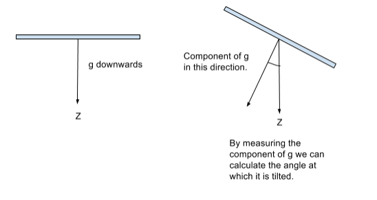
To give an idea let’s just consider the Z-axis. When the MPU6050 module is horizontal with respect to ground we get a measurement of 9.8 m/s^2 in the downward direction. When it’s tilted the we will able to measure a component of g using which we will able to calculate the angle at which it is tilted. To give a clearer idea please refer to the diagram below.

How did we make our project?
Now that we have a clearer picture of how MPU6050 works we can move on to the project that we made. We connected the MPU6050 to arduino via I2C. The SCL and SDA (used in I2C) are connected to pins A5 and A4 respectively. The VCC and ground will be connected to 5V and ground of Arduino.
The Arduino code can be found over here). Download this zip file and extract it. Take the file MPU6050 and paste it in Libraries directory of Arduino. Next open Arduino, go to File, Examples, MPU6050, Examples, MPU6050_DMP6 and run it. Open Serial Monitor and you should see the raw accelerometer values. Be sure to set the baud rate of the serial monitor to 115200.
Sneak peek into the code
This program makes use of the MPU6050 library developed by Jeff Rowberg which helps us to easily interface MPU6050 with Arduino board. The MPU6050 library has a number of built in functions but the function we are using is to get the yaw, pitch and roll angles is ‘dmpGetYawPitchRoll’. Once the sensor returns these values an interrupt is fired and the values of these sensors is printed on the Serial Monitor. But before running this part we setup the I2C connection between MPU 6050 and Arduino, test this connection and initialize the DMP package (DMP stands for Digital Motion Processing). DMP is used by MPU6050 to process the raw values outputted by MPU6050 and get the yaw, pitch and roll angles from them. Then, we showed the output in a software known as ‘Processing’, which was basically a picture of a plane, which tilted the way we tilted the MPU6050!
For further details on this project please refer to this excellent tutorial.
Hope you had a great time reading this and were able to learn something new!
